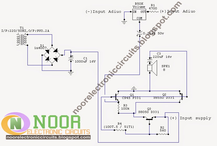
This is the circuit diagram of a simple three transistor audio amplifier.The circuit will work well with an 8 ohm speaker too, but the volume will be a little less.
Wednesday, 29 October 2014
Sunday, 8 December 2013
Transistor Tester Circuit
This is a very simple transistor tester circuit the circuit can be used to test NPN and PNP transistors. The
voltage source is a 6V power supply which is 230V AC to 6V step down transformer. It is essential to put
the transistor leads in right direction like transistor emitter to circuit emitter where (E) is markedtransistor
base to circuit base marked (B) and transistor collector to circuit collector marked (C). The switch S1 is a
rotary switch to choose a correct base resistor for under test transistor. The green LED will glow when an
under test NPN transistor is working correctly and red LED will glow when an under test PNP transistor is
working correctly.
USB Powered LED Night Lamp Circuit
These days, we can see various USB gadgets on the market. today we try to make USB powered LED night Lamp. You can use it
as a table lamp by connecting to PC or Laptop. This circuit operates using USB port as its power source. D1 indicates connection
with USB port. The computer USB port able to provide up to 500mA current. But here, we use 100mA current for this circuit,
because it's very safely to your computer.You must be confirm accurately the pins (Positive and Ground leads) of USB port.

Components:
S1 – Switch (Can be use to turn ON/OFF lamp)
R1, R2 – 560O/0.25W
R3 – 1K/0.25W
D1 – Red mini LED
D2 – 1N4007
D3...D8 – 6 x 8mm White LEDs
C1 – 0.01f (103) Ceramic
Q1 – BC547 or BC548
Please Note:
You must be confirm accurately the positive & ground leads of USB port before build the circuit.
Check again the positive & ground leads of USB port before connect it with PC.
Don't short circuit.


Subscribe to:
Comments (Atom)